A highly specialized, process-driven approach to design-build services
Complete solutions for complex projects.
With numerous services on one team and a deep understanding of the demands of the life sciences industry, you can trust us to meet your project’s regulatory and process standards the first time.
$30.9M
in Life Sciences experience1.9M
Life Sciences square feet200+
Life Sciences projectsYou'll be in good company.

Partner with the experts.
We're ready for every facility challenge and partner with you to provide:
Proven engineering and construction management on one team
Expertise in the regulatory standards of the life sciences industry
Experience planning and executing on cGMP projects
Detailed planning with contingencies to deliver projects on time
Top-rated safety program and zero-accident culture
Expert solutions for life sciences clients in North America.
Pharmaceutical/Medical Device
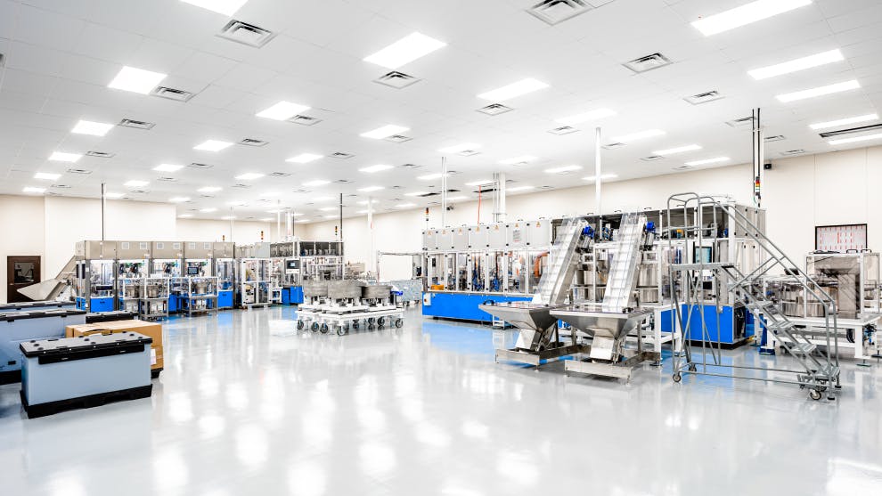
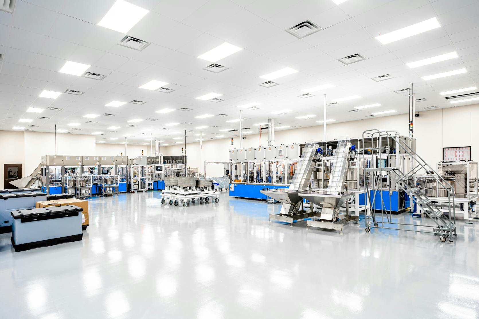
C1S was contracted to complete a design-build project encompassing a 55,000-square-foot pre-engineered metal building from the ground up. This versatile structure integrates production, logistics, and expansive warehouse spaces, with a structural steel second floor mezzanine area dedicated to housing mechanical equipment. Demonstrating unparalleled adaptability, the project team seamlessly transitioned into the high-priority realm of Operation Warp Speed. Leveraging our expertise, we converted a 35,000-square-foot warehouse into a controlled environment tailored for syringe manufacturing. This transformation involved the integration of seven cutting-edge syringe molding pieces of equipment, complemented by the installation of three additional assembly lines.
We help you stay on top of the latest life sciences issues.


Are you experiencing heating, cooling or pressurization issues in your mission critical facility? As the facility manager, the last thing you need is an HVAC issue leading to product contamination or a production shutdown. If you are unsure as to the precise cause of these issues, you should consider hiring a licensed engineer to perform an airflow study to diagnose the situation. An airflow study allows you to pinpoint root causes and develop clear solutions to address your HVAC problems before they become issues impacting your operations or the comfort and well-being of your valued employees. The study is done at a fraction of the cost of the eventual repair, and they save you money by properly addressing the problem the first time. For what can be just 1-3% of the eventual capital expenditure, this assessment of your HVAC gives you a detailed remediation report to optimize your operations, and it provides you with the business case you need to get an approved Capital Allocation Request. How it Works The airflow study will consist of a site walk-through with your staff, subsequent field work by the engineers and data analysis of temperature, relative humidity, air particle counts, and air changes compared against room specifications. The main objectives are to evaluate the existing conditions of equipment on site, evaluate the HVAC/air distribution issues in the facility and provide you with budgetary pricing for the proposed recommended fixes. Over the years, the manufacturing clients of the C1S Group have benefited from us providing this crucial HVAC assessment. Recommendations vary from simple, quick fixes that restore system optimization and increase energy efficiency to large scale change-outs of existing equipment. Whatever your needs, your company can benefit from working with the C1S Group and our holistic approach. We can work with you from the initial assessment through any potential design and construction phases that might be necessary. Some of the benefits you could see: Reduced Risk of Production Shutdown Reduced Risk of Product Contamination Energy Savings Improved Employee Comfort and Well-Being
The Standards and Other Basics of Cleanroom Design Cleanrooms are an important component of industrial manufacturing and laboratories, used extensively within the technology, pharmaceutical and medical industries. Accordingly, a cleanroom design must be created according to exact requirements that are spelled out in internationally recognized standards. This blog is a first in a series discussing the design and construction of cleanrooms and will cover these standards, the utility matrix that guides the design process, and the equipment included in the mechanical systems that support the cleanroom. Future blogs will discuss mechanical equipment in depth, examine how to maintain the quality of the air within the cleanroom and review the protocols that must be maintained during construction to insure the integrity of the finished cleanroom. Cleanroom Standards For many years individual countries set standards for cleanrooms, which created confusion and inconsistency. Today, cleanrooms are defined by the International Standards Organization under the standard ISO 14644. This standard defines a cleanroom as “A room in which the concentration of airborne particles is controlled, and which is constructed and used in a manner to minimize the introduction, generation, and retention of particles inside the room and in which other relevant parameters, e.g. temperature, humidity, and pressure, are controlled as necessary.” As the definition implies, the standard contains several sections covering all aspects of cleanrooms, including classification of air cleanliness, testing, monitoring, evaluation, measurement and what constitutes an airborne molecular contamination. The following figure illustrates the scope of the standard. ISO 14644 STANDARDS 14644-1: Classification of Air Cleanliness 14644-2: Testing and Monitoring to prove continued compliance to ISO-14644-1 14644-3: Methods of Evaluation and Measurement 14644-4: Design, Construction, and Start-Up of Facilities 14644-5: Operations 14644-6: Terms and Definitions 14644-7: Mini-Environments and Isolators 14644-8: Airborne Molecular Contamination Cleanroom classifications are based on the number of particles equal to and greater than 0.5 per micron (µm) in one cubic foot of air. The task performed in the room dictates the standard of cleanliness required for the space, so the more susceptible the product produced is to contamination, the higher the standard. An ISO Class 1 cleanroom must have a particle concentration of no more than 0.01 per/cu.ft. @ 0.5 micron. Similarly, a Class 5 cleanroom could have as many as 100 particles per/cu.ft. @ 0.5 micron. The highest classification in the standard is a generous Class 9, allowing for one million particles per cubic foot. The standard also determines the type and frequency of testing, such as for particle count, air pressure and air flow, required to be in compliance. Finally, the cleanroom design must account for the equipment and finishes used because each contributes to the amount of particulate in the space. ISO 14644-1 OVERVIEW ISO 14644-1: Particle Concentration (#/cu.ft. @ 0.5 micron) ISO 1.0: 0.01 ISO 2.0: 0.1 ISO 3.0: 1 ISO 4.0: 10 ISO 5.0: 100 ISO 6.0: 1,000 ISO 7.0: 10,000 ISO 8.0: 100,000 ISO 9.0: 1,000,000 The Utility Matrix Successful cleanroom design begins with a high level of participation and involvement by the facility owner, the tool owner and the facility management team. The greater the cooperation, the easier to manage construction costs and, eventually, annual operation costs. Guiding the design process is the Utility Matrix (UM). Developed with the owner’s participation, this is the single most important document and you must get a sign off on this document before proceeding into design. The UM can be developed directly by the owner, if the expertise exists in-house, or an outside consultant can be brought in to assist in development of a tool layout and process flow. Once this is completed, the tool list and UM is established and forms the baseline for design. The tool matrix lists all utilities that are to be used by the tool set and system designers will then take the information from the finalized UM to design the specific support systems. These will typically include: UPW plant Bulk gas and chemical source and distribution systems Specialty gas storage area and distribution system Industrial waste treatment plant Exhaust air treatment and distribution systems Make up air system Cleanroom recirculation air cooling and filtration system Support rooms recirculation air systems Normal and emergency power systems Process cooling water Process vacuum system Mechanical Systems in Cleanrooms The largest component of the construction cost of a standard cleanroom facility is the HVAC/Mechanical system and will be the primary focus of this and subsequent blogs. Constituting approximately 25 percent of the total facility cost, the HVAC/Mechanical systems consist of the following: Recirculation Air Systems (cleanroom and support): 31% Chilled Water System ( chillers and dist piping): 31% Process Exhaust (scrubbers, VOC abatement, fans, ductwork): 18% Hot Water System (boilers and hw/steam dist piping): 13% Make Up Air System: 7% Total: 100% Understanding the makeup air (MUA) and exhaust air requirements is necessary in order to determine the size and quantity of other elements of the HVAC/mechanical systems, so the design process for these systems starts there. Consult the UM to find the Exhaust (EXH) flow rates and then determine the MUA quantities needed to cover the air exhausted from the room plus surplus to pressurize the space. This is expressed as MUA=EXH+10%. The MUA requirement dictates the amount of chilled water and heating water required from the central plant, thus affecting the overall size and number of chillers and boilers. Likewise, the exhaust air quantity has impact on heat removal from the cleanroom and impacts the size of the sensible cooling coils and recirculation air system. When it comes to designing the HVAC/Mechanical systems in a cleanroom, remember there is no single formula or right answer to an owner's specific requirements. Each project must be looked at individually and systems compared based upon cost, system type, owner sophistication and process requirements. Our next blog will look into the specific details of the make-up and exhaust air systems and the filters required to maintain the purity of the air in the cleanroom.
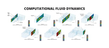

Computational Fluid Dynamics Modeling (CFD) is the art of modeling the air within a space as a fluid and analyzing how different variables such as air flow patterns, velocities, temperatures, and pressures can be affected by a room’s design and internal components. Utilizing both mathematical formulas and principles of physics the design team can model and view a representation of the phenomena related to a rooms’ function. CFD modeling is a critical pre-construction step used by engineers to compare the results of various facility options during the design phase. The CFD model allows engineers to optimize the space and pinpoint potential problems early which results in time and money savings in the design phase as well as reduced construction costs. How it Works Pre-Processing This is the beginning stage where the designers build out the geometry of the space and any associated equipment or obstructions within. Once the basic geometry of the room is modeled the team will start assigning boundary conditions such as flow velocity from a supply grille, supply air temperature, mass flow rates of the return grille(s). As the project progresses and an equipment plan is formed, designers export the equipment out of the building information model and into the CFD model. A heat flow rate associated to the equipment’s equivalent heat load distribution to the space is assigned to the equipment in the model and simulated. Solving Once the information has been set up within the program and the boundaries and internal conditions are set the software can begin to model the conditions assigned in the Pre-Processing stage. The initial conditions will be set and when the simulation starts the team is able to view a visual representation of the air’s fluid dynamical properties. By analyzing values such as velocity, pressure, temperature, and airflow, the team can identify, address and solve design problems that in normal design conditions may be overlooked. Post-Processing Once the results have been returned as values the team can then plot them as scaled color plots, contour plots and various other appropriate representations that can be used to enhance the overall design understanding of the space and advert any negative resolutions that were discovered during the testing process. These can also be shared with the client to detail why certain design changes were needed in a space, especially if the design change may seem odd or nonstandard at the time. Limitations of CFD Modeling Like all models, a CFD model is only as good as the inputs and assumptions used to create the model. It is imperative to hire a qualified, experienced engineer with the knowledge to gather a complete set of data and verify with field measurements where possible. Partnering with a diligent and thorough engineer will ensure the integrity and validity of your model for effective decision making. How Using CFD Modeling Upgrades the Design Process The modeling allows the designers to visually simulate the airflow patterns, temperature and pressure within a space. This enables the team to identify any low-pressure areas, hot spots and areas where the air tends to circulate but not escape and return. Prior to the advent of CFD modeling, engineers and designers often had to make the best assumption that they could with the information present, and using best practices assume the way the air would flow through the space. Now with CFD modeling, the design team can see exactly where the air will go and how to make the design the most efficient without costing the client change orders after the construction has started. For a C1S client, the engineering team was designing a cleanroom. While there are no standards for locating supply and return grilles, it was deemed appropriate to place the grilles on one wall assuming that the air would disperse across the room and circle back to the return grille. After the CFD model was complete, it was discovered that the velocity was high enough to disperse the air across the room, however the model indicated an entrapment of air in the corner of the room caused by the high velocity air which resulted in a lack of return air leaving. Being able to identify this before the room was being constructed saved the client unnecessary cost increases and delays. The design team was able to simply move the vent to the other side of the room to properly circulate the air.

Learn about the C1S Group Cleanroom design and construction process.
Find the right solution for your life sciences project.
You can also give us a call at:
972.829.0148